California is already experiencing the sweeping changes of interconnection rule 21 phase 1, but what about the next two phases of the tariff? The Smart Inverter Working Group (SIWG) has already publicly released recommendations for the next two phases which detail communication requirements and utility-controllable smart meter functionalities.
Phase two is about connecting distributed energy resources (DERs) to the electric utility through a standardized communication protocol. This phase is expected to come into effect in early 2019, from which time all interconnection requests will have to comply with the new communications standard.
It should be noted that not every smart inverter needs to comply individually with the standard communication protocol. For example, a system comprised of multiple photovoltaic (PV) panels each with its own microinverter can be handled as an aggregate DER and communicate as if it were a single PV + smart inverter installation.
The type of information DERs are required to send to utilities can be categorized into three groups:
- Administrative Data – DER system ID, system ratings, available functions
- Monitored Data – Real-time measurements, state of readiness
- Error conditions – Indication of any failure to comply with requirements within the agreed timeframe, alarms noting shutdown or failure to restart with the associated reason
Phase three seeks to harness the communication system set up in phase two to give utilities direct control over smart inverter operation. As opposed to phase one, where smart inverters are required to perform functions autonomously in response to system parameters, phase three involves more directed action.
Utilities will control new phase three operation modes by providing smart inverters with the following details:
- Mode (Dynamic Reactive Current Support, Limit Active Power)
- Status (Enable, disable)
- Time (Right now, in three hours)
- Parameters (ramp-rate, voltage setpoint)
Furthermore, utilities will be able to fine-tune the behavior of the phase one autonomous inverter functions by specifying new characteristic curves.
Some of the powerful new smart inverter operation modes included in phase three are:
Dynamic Reactive Current Support Mode
This mode involves changing reactive power output quickly to counteract transient voltage fluctuations. This should not be confused with the Dynamic Volt/VAR function specified in Phase 1, see the table below for a comparison:
| Function | Introduced | Action |
| Dynamic Volt/VAR function | Phase 1 | Reacts slowly to abnormal voltage levels |
| Dynamic Reactive Current Support Mode | Phase 3 | Reacts quickly to any sudden change in voltage |
Table 1: Comparison of Dynamic Volt/VAR and Dynamic Reactive Current Support
The dynamic volt/VAR function responds in about 5 seconds when voltage magnitude deviates from defined setpoints. Dynamic reactive current support acts faster and, instead, responds to deviations from the moving average; its purpose is to minimize high-frequency voltage events regardless of whether the long-term voltage magnitude is close to nominal voltage or not. The figure below illustrates the difference between the two operations.
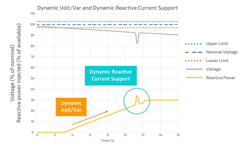
As shown in the above figure, the behavior of the dynamic volt/VAR function is characterized by a gradual increase/decrease in reactive power output in response to an abnormal voltage, whereas dynamic reactive current support acts on a shorter timescale in response to quick changes in voltage.
The specific response of the dynamic reactive current support mode is characterized by the following diagram which includes configurable parameters to fine-tune its operation.
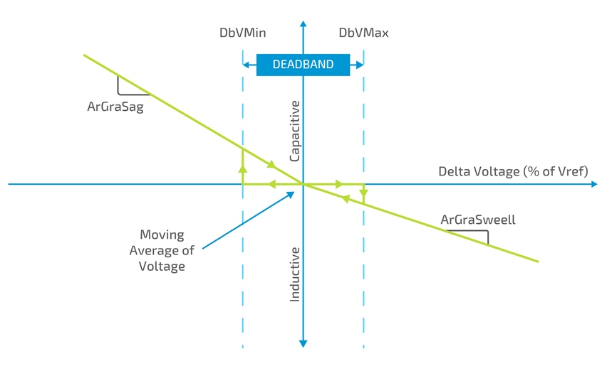
When an electric utility wants to enable the dynamic reactive current support mode, it will need to send the enable request along with the scheduled initiation time and define the parameters shown in the above figure.
Limit Active Power Mode
This mode involves the utility sending an order including:
- An active power setpoint (As a percentage of maximum available power)
- A ramp rate (The rate at which the maximum power output must decrease to the setpoint)
DERs must begin to observe the reduction in maximum power output within 30 seconds of the scheduled start time of limit active power mode. It should be noted that if a DER is exporting less power than it has available when it receives this request, it may not need to reduce its power output at all.
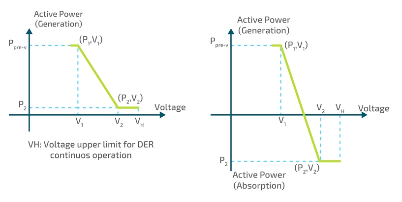
Volt-Watt mode
This mode is yet another method to control system voltage. As one would expect, it involves reducing power output for overvoltage conditions. For DERs with storage capability, utilities may even request that the system start absorbing energy.
The following figure demonstrates the volt-watt characteristic with all the relevant parameters.
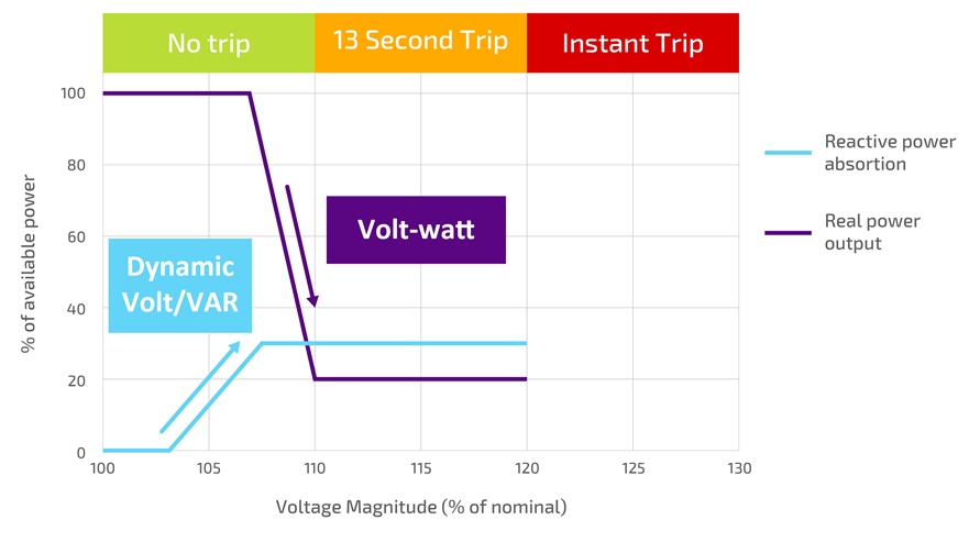
Note that with the addition of this new mode, there are now four smart inverter operations available for controlling overvoltage(1):
- Dynamic volt/VAR
- Volt-watt
- Voltage ride through
- Voltage trip
The following table shows how a smart inverter using these four operations would respond to system voltage as it steadily increases above nominal level. Please note that the voltage values used are reasonable default settings but network operators may specify different values for their particular needs.
| Voltage (% of nominal) | Voltage Region | Overvoltage action |
| 100 – 103.3 | NN | N/A |
| 103.3 – 107 | Reactive power absorption ramps up to 30% | |
| 107 – 110 | Real power output ramps down to minimum (volt-watt mode) | |
| 110 – 120 | HV1 | Voltage ride through zone. Will trip after 13 seconds if voltage doesn’t return to NN |
| 120+ | HV2 | Instant trip |
Table 2: Overvoltage control operations in phase three
Utilities within California and in the rest of the US will soon have the power to remotely control DERs and exercise advanced control over electricity networks. If you want your company to keep up with the quickly developing world of smart grids, you will need to make some key changes to the operation of your business.
Enhance Analytics
There are a growing number of independent actors in the generation space thanks to the uptake of DERs, so anticipating how networks are going to behave is becoming a tougher task which can only be solved using more advanced tools. For this reason, many utilities are beginning to invest in simulation and analytic technology to determine which settings are suitable to provide the best balance of network stability and DER generation capacity.
Upskill and Expand Field Work Resource
As part of phase two, significant communication systems will need to be set up to support online DERs. Traditionally, the demand for communication technicians in electric utilities has been low, but if you have just carried out an AMI rollout then you may already be ramping up expertise and human resources in this key area. Furthermore, the rate of PV uptake may lead to an increase in network reinforcement work as required to support peak midday power generation.
Setup DER Workflow
A robust system must be developed which controls the lifecycle of a DER installation including application, network study, and field work while managing the associated accounting and billing processes. Furthermore, the system must take into account that the rules applied to each connecting DER vary depending on application date, generation capacity, and the generator technology (e.g three-phase synchronous generator, induction generators, PV + inverter)
The rate at which new legislation comes into effect these days leaves little room for companies which are slow to adapt. If you are ready for the smart grid revolution but you feel that your business systems are holding you back, it may be time to consider a technological upgrade for your company.
Electric utilities outside California are lucky in the sense that they have some advanced warning about what lies in store for the future of the industry. To make the most out of this opportunity, these companies must make early preparations so that the sweeping changes of DER legislation don’t catch them off guard.
Smartflex is a comprehensive CIS and Field Service solution which covers a wide range of business processes and gives you the flexibility to keep up in a rapidly changing regulatory landscape. With an adaptive tool to create new workflows, you can easily manage complicated DER application processes which tie into multiple business functions, harnessing a centralized hub for operations in the office and on the field. A truly integrated and mobile workforce can give you the power to get the most out of your fieldwork resource at this critical juncture in the path towards the future.