Smart grid technology is gaining ground in the United States with California leading the charge. The state’s new interconnection rule 21 is redefining the role of distributed energy resources (DERs) in the modern electricity network by specifying advanced features that DER-connecting inverters are expected to perform. These “Smart Inverters” are already providing enhanced network support through a range of autonomous functions and their value to the network is only expected to grow as further phases of rule 21 come into effect.
The rest of the US is looking closely at California for thought-leadership in the growing field of smart grids, so rule 21 is sure to have a huge influence on shaping the future of DERs in networks across the country.
The continuous development of rule 21 is handled by the Smart Inverter Working Group (SIWG), which has been finding innovative ways to provide network stability with smart inverter technology since 2003. The rule is made up of three phases, with Californian electric utilities each maintaining their own version of the rule and incorporating the new phases as they become available.(1) The three phases are as follows, with the implementation date shown in brackets:
- Phase 1 (Already in effect) requires inverters connecting distributed generation to be “Smart Inverters” complying with standards which specify a set of power quality requirements and auxiliary functions which provide support to the grid. A full list of complying inverters can be found here.
- Phase 2 (Early 2019) sets up communication requirements for inverters, making them a part of the IoT and remotely controllable by utilities.
- Phase 3 (Sometime in the future) will specify further advanced functionality, harnessing the communication links set up in phase 2.
With phase 1 already in effect, DER connecting inverters in California are now required to act autonomously and intelligently to support the grid. These new inverter functionalities give utilities an unprecedented ability to apply new smart grid practices on their network; thereby reducing the amount of upgrade work required to facilitate the increasing number of DER connections. Some of the most important features of phase 1 are:
Voltage Trip and Ride Through
Previously, grid-connected inverters have been required to trip almost instantly for abnormal system voltages or frequencies. While this system has worked well for a time, it is not appropriate for networks with high photovoltaic (PV) penetration.
Momentary events such as faults or the switching of large loads can affect voltage magnitude. If many grid-tied inverters simultaneously trip in response to an abnormal voltage level, the cumulative effect can cause a large and sudden drop of generation, which may lead to a chain reaction and further destabilize the network.
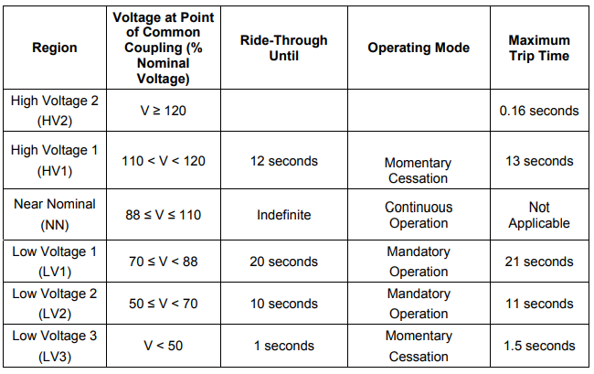
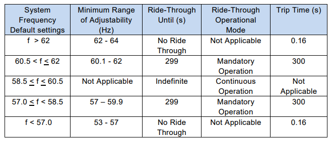
To prevent this from happening, smart inverters compliant with rule 21 are required to continue operating or “ride-through” during momentary voltage deviations. These inverters will eventually trip if the voltage remains outside the Near Nominal (NN) range for too long. The voltage ride-through and tripping details are shown in the following table:
Dynamic Volt/VAR Operations
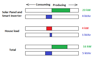
Basic photovoltaic power inverters convert power from DC to AC while ensuring that the resultant current waveform is in phase with system voltage. At unity power factor(2), no reactive power is consumed or produced by the inverter.
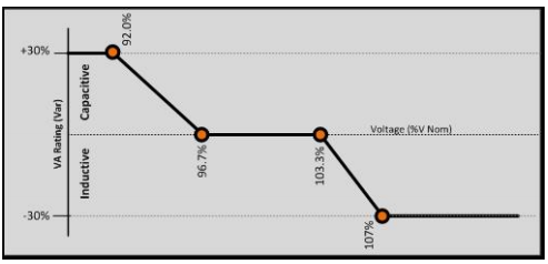
Smart inverters, on the other hand, can inject or absorb reactive power in addition to their primary function of converting real power from DC to AC. With rule 21, PV power inverters are now required to use this functionality in order to assist the regulation of system voltage. The following table and graph show the required dynamic volt/VAR operations.
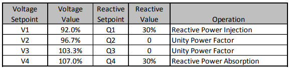
It should be noted that the dynamic volt/VAR function will reach maximum reactive power injection/absorption before the voltage deviates from the Near Nominal (NN) region shown in Table 1.
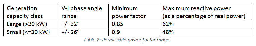
Typically, smart inverters for photovoltaic generation can provide a power factor (PF) as low as 0.8, which is to say that for each 10 kW of real power exported, the inverter can absorb or inject up to 7.5 kVAr of reactive power. However, according to rule 21, smart inverters must maintain a minimum power factor as per the following table, which places a limit on the amount of reactive power support available.
As with the voltage ride-through and trip functions discussed in the previous section, the dynamic Volt/VAR function responds to system voltage. The following graphic demonstrates how these three functions work together to combat abnormal voltage levels.
- Dynamic Volt/VAR – This function is used first to correct abnormal voltages within the NN region, however, it will never reduce active power production.
- Voltage Ride Through – If voltage deviates from the NN region, smart inverters will continue to provide reactive power support while “riding-through” the abnormal voltage for a time.
- Voltage Trip – If the voltage does not return to near-nominal, the inverter will trip, cutting off all real power exports until the system has returned to normal conditions for a reasonable period of time.
Thanks to these functions, significant voltage control can be achieved without negatively impacting customers’ active power generation. With dynamic volt/VAR control and voltage ride through, networks will be able to host more distributed generation while reducing the number of smart inverter tripping operations.
There is, however, a notable problem with the dynamic volt/VAR function proposed in phase 1. With reference to table 3, the maximum amount of reactive power to be produced or absorbed by a smart inverter is not to exceed 30% of the available reactive power (This refers to the maximum amount which can be achieved without curtailing real power output). While on the first inspection, this sounds like good news for customers, it may cause problems at midday when PV generation is at its peak and the system is at risk of overvoltage. This situation is discussed in the example below:
Bob’s House
Bob has a 5kW PV system installed in a neighborhood full of solar power. At midday, his solar panels are producing the full 5 kW output and the network is suffering from overvoltage due to excessive generation. According to the dynamic volt/VAR function, his inverter is required to absorb reactive power up to 30% of its available capacity while not reducing the power factor below 0.9.
A comparison of reactive power absorption scenarios for Bob’s smart inverter are shown in the table below:
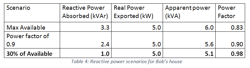
As per the 30% limitation, Bob’s smart inverter is required to absorb only a modest 1.0 kVAr, which is less than half the of the reactive power which could be achieved at the minimum power factor of 0.9.Table 4: Reactive power scenarios for Bob’s house
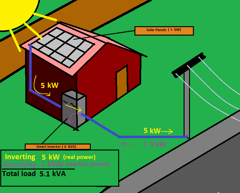
With his smart inverter operating at a just 85% capacity, he can assist in lowering system voltage while exporting the full 5 kW capacity of his photovoltaic system.
If the smart inverters in Bob’s neighborhood fail to correct the overvoltage by absorbing 30% of available reactive power, the system voltage may leave the NN region and eventual cause a trip. If this happens regularly, it could cause a significant impact on Bob’s energy exporting revenue.
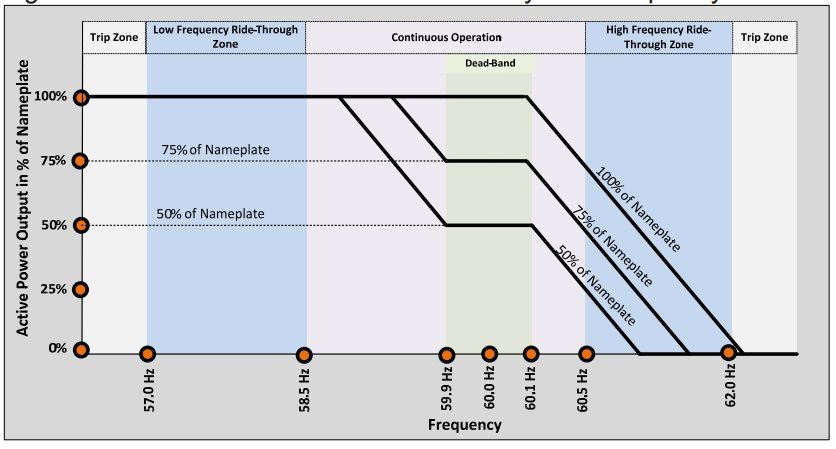
Frequency Ride Through, Frequency Trip, and Frequency-Watt control
Similarly to voltage ride through, smart inverters are required to continue operation during temporary periods of abnormal frequency in order to maintain grid stability.
For extended periods of abnormal frequency, the inverter is required to trip after a large time delay. For extreme deviations in frequency, the inverter must trip quickly.
Furthermore, to help the network deal with periods of overgeneration or overloading, inverters are required to decrease real power output in response to high power frequency and, if possible, increase real power output in response to low power frequency.
These new autonomous features give smart inverters a chance to react dynamically to network conditions in order to stabilize voltage and frequency. With this support, networks can host more photovoltaic power generation and smart inverters are less likely to trip. This is great news for customers because the increased uptime of their inverter means more energy being exported to the grid.
As technology and interconnection policies develop further, the interaction between customer and utility is becoming increasingly complicated. To help customers stay informed in this rapidly changing climate, utilities are under more pressure than ever to provide timely and accurate information through a range of interfaces.
The rapidly growing trend of web portals will be increased further by the ongoing development of rule 21. When phase two comes into effect, smart inverters will join smart meters in being connected to the utility through the Internet of Things (IoT). With real-time information from both these devices, utilities will be able to provide enhanced insights to customers about their ongoing technical and commercial interactions with the utility.
As specified in the legislation for rule 21, each connection must undergo a thorough application process. Part of this process includes a study to ensure that the network is in a condition to host the new generation capacity without unbalancing transformer loadings or exceeding equipment ratings. In some cases, it may be found that network upgrade works are required to facilitate the new DER connections being requested.
In any event, the network operator will often need to carry out some field work, even if it is just the installation or upgrade of the customer’s smart meter. Overall, the connection process can take months and involve a wide range of business functions such as fieldwork, commercial operations, network studies and customer relations management.
As a network operator in the quickly changing regulatory environment of the United States energy sector, it is natural to be thinking carefully about how your company is going to adapt and grow to meet the future demands of the industry. Many companies have found that by replacing their core business systems with a flexible CIS and Field Service solution, it becomes easier to adapt to regulatory change while constantly improving customer experience.
Smartflex gives you the possibility to easily develop and configure business processes which allow seamless interaction between key areas such as smart metering, billing, field service, and customer web portals. With a flexible and easy-to-use system which covers a broad range of business activities, your company can lead the industry forward into the exciting future of smart grids.